Published
Reviewed
For a fibre receiver, select PIN or APD from the received optical power, required speed and receiver noise. A PIN design is a practical starting point when it meets the sensitivity target. Consider an APD when weak signals are limited by amplifier noise. For optical power monitoring, also check whether you need a tap detector rather than a complete data receiver.
What is the difference between PIN, APD and TIA?
A PIN photodiode converts incident light into current without avalanche multiplication. An avalanche photodiode (APD) adds internal current gain. A transimpedance amplifier (TIA) converts detector current into voltage and can follow either detector type. Therefore, an APD-TIA module combines two functions; the name alone does not specify its bias controller, connector or pinout. See the Hamamatsu InGaAs PIN and APD technical note and TI's explanation of TIAs.
Does APD gain always improve sensitivity?
No. Avalanche multiplication increases the signal before the external amplifier, but it also adds excess noise. InGaAs APD gain changes with reverse bias and temperature. Increasing gain can lengthen the multiplication time and reduce response speed. The best operating point balances signal, detector noise, amplifier noise and bandwidth; it is not necessarily the highest gain. Hamamatsu describes these relationships in its gain, noise and response sections, pages 10–13.
For procurement, ask for performance at your minimum received power and maximum expected input. A detector that resolves the weakest signal must also work at the other end of the input range. Select the complete receiver for the job rather than assuming that “APD” means better performance under every condition.
APD bias and TIA supply are different specifications
The TIA supply powers the amplifier. The APD reverse bias sets the detector's operating point and affects its gain. Do not use a TIA supply value as the APD bias setting.
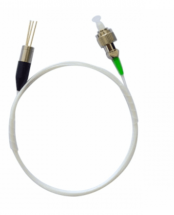
For example, DTNT's 1.25Gbps or 2.5Gbps InGaAs APD-TIA pigtailed detector lists a 1260–1620nm wavelength range. Its TIA supply is 3.0V minimum, 3.3V typical and 3.6V maximum. A separate APD operating-voltage row gives VBR − 3V in its typical column for best sensitivity, where VBR is the APD breakdown voltage. These rows describe different functions. The 3.3V typical supply is not a universal APD bias.
For this module, confirm the device-specific bias setting, its temperature control requirements and the connection drawing before electrical integration. A product photograph does not establish the pin assignment.
Compare sensitivity and bandwidth under matching conditions
Receiver sensitivity is the minimum optical input needed to meet a stated bit-error ratio (BER). Compare values with the same wavelength, data rate, extinction ratio, test pattern and operating conditions. A responsivity value in A/W is not the same measurement as receiver sensitivity in dBm. Analog Devices explains the BER basis of receiver sensitivity; its ADN2880 datasheet shows why wavelength, responsivity, extinction ratio and BER accompany an optical sensitivity claim.
Bandwidth also needs context. DTNT's APD-TIA table gives small-signal bandwidth of 1.65GHz minimum, 2.05GHz typical and 2.5GHz maximum at multiplication gain M = 9. These are bandwidth figures under that condition, not three interchangeable data rates. For a receiver design, photodiode capacitance, TIA gain and amplifier bandwidth also interact, as described in the TI bandwidth discussion.
A PIN tap detector serves a different purpose
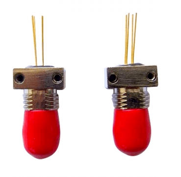
DTNT's InGaAs PIN photodiode table lists an operating wavelength of 1260–1650nm and a 2% tap ratio at Tc = 25°C. The tap ratio matters: this is a tap-device specification, not a BER sensitivity test for a complete data receiver. Its responsivity must not be treated as a direct PIN-versus-APD receiver comparison. Confirm the optical reference point and intended monitoring function. The page includes a package and pin drawing for mechanical and connection review.
What should a receiver quotation include?
- The job: data reception or power monitoring, wavelength, and minimum and maximum optical input.
- The signal: data rate or analogue bandwidth; for data links, the required BER, extinction ratio, test pattern and continuous or burst operation.
- The electronics: detector type, available TIA supply, APD bias control if needed, output interface and pin assignment.
- The assembly: fibre and connector, pigtail length or receptacle, mechanical envelope and operating temperature range.
Browse the InGaAs APD and PIN photodiode range and include the relevant product URL when you request a quotation.