
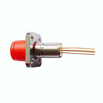
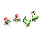
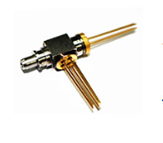
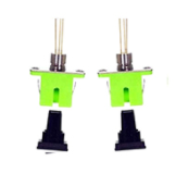
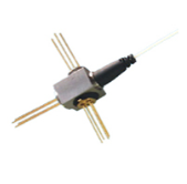


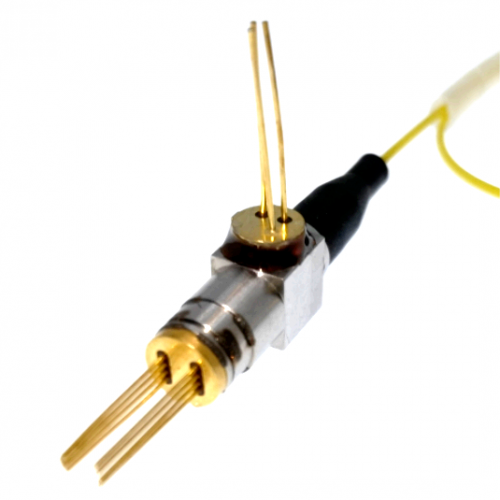
Tunable Laser Optical TOSA
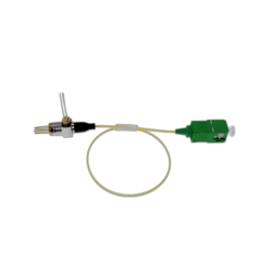
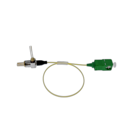
Our tunable Laser had assembled with pigtail as Transmitter Optical Sub-Assembly (TOSA) , and which is based on an 8-pin TO-CAN package,that provide the competitive cost to customers.
Our Tunable laser comprises a V-cavity edge-emitting tunable laser, a power monitoring photodiode, an isolator, and a TEC controller, with an LC connector. Currently it can provide up to 16 channels at 100GHz spacing or 32 channels at 50GHz spacing in C- or L- band (other wavelength bands available on request), with a customer specified starting wavelength. The laser chip can be operated in semi-cooled condition at 40-60℃ while the ambient operating temperature is between 0 and 70℃。
Key Features
Up to 16 channels at 100 GHz spacing or up to 32 channels at 50GHz spacing
C- or L-band
Simple tuning algorithm
2.5 -10 Gbps direct modulation
Low-cost TO-can based optical subassembly
Applications
NGPON2
WDM-PON
Optical interconnects
DWDM sparing
Pin Assignments
| Specifications | |||||||||
| Parameters | Min. | Typ. | Max. | Unit | |||||
| Optical Output Power | 0 | dBm | |||||||
| Ambient Operating Temperature | 0 | - | 70 | ℃ | |||||
| Gain Forward Bias Current | 25 | 30 | 50 | mA | |||||
| Channel Selector Current | 20 | - | 100 | mA | |||||
| Fine Tuning Current | 20 | 25 | 40 | mA | |||||
| LD Forward Bias Voltage | - | - | 2.3 | V | |||||
| Modulation Data Rate | 2.5 | Gbps | |||||||
| Wavelength | C / L band | ||||||||
| Channel Spacing | 50 or 100 | GHz | |||||||
| Number of Channels | 16@100GHz | ||||||||
| 32@50GHz | |||||||||
| Side Mode Suppression Ratio | 35 | 38-40 | - | dB | |||||
| Optical Isolation | 25 | - | - | dB | |||||
| Relative Intensity Noise | - | - | -135 | dB/Hz | |||||
| Power Monitor Current | 20 | - | 500 | μA | |||||
| Power Monitor Dark Current | - | - | 100 | nA | |||||
| TEC Current | - | 0.5 | 0.9 | A | |||||
| TEC Voltage | - | - | 1.2 | V | |||||
| Total Power Consumption (PLD + PTEC) |
- | 0.8 | 1.5 | W | |||||
| Thermistor B constant | - | 4050 | - | K | |||||
| Thermistor Resistance @25C | 9.5 | 10 | 10.5 | kΩ | |||||
| Pin | Symbol | Description | ||
| 1 | TEC+ | TEC anode | ||
| 2 | Rth | Thermistor | ||
| 3 | LD3+ | Fine tuning | ||
| 4 | PD- | PD cathode | ||
| 5 | LD1+ | Gain bias and modulation signal |
||
| 6 | Common | LD3-/LD1-/PD+/L D2-/Rth |
||
| 7 | LD2+ | Channel selector | ||
| 8 | TEC- | TEC cathode | ||